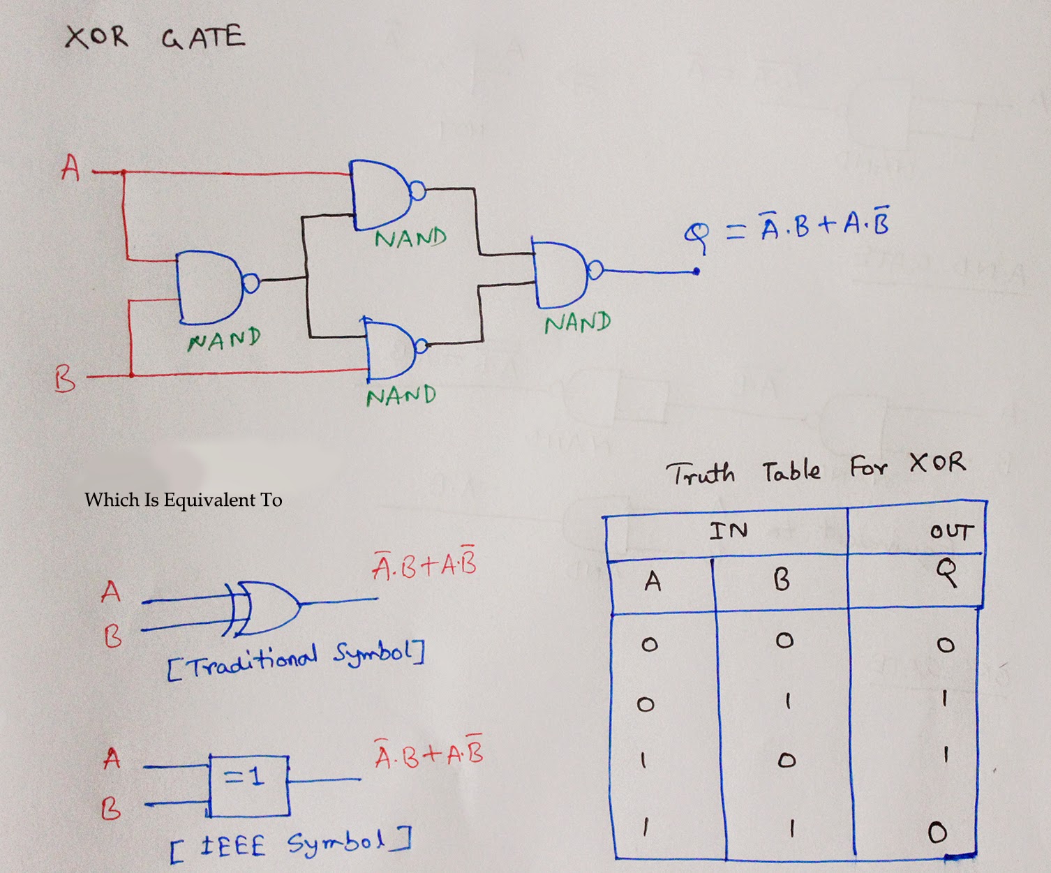
2 Input Or 3 Input Nand Gate Circuit Diagram
Cmos nand circuit diagram wiring view and schematics diagram Circuit diagram of nand logic gate Lab 1 l-edit
Solved 1. Construct the 2 input NAND gate circuit as shown | Chegg.com
Logic nand gates 2 input nand gate layout 7400 nand gerbang logika ttl datasheet compuertas circuitos 74xx cmos satu entradas jiwa salam
2 input nand gate cmos schematics pdf
Two input nand gate. basic two input nand gate: figure 3 show theLogic nand gate tutorial with nand gate truth table Circuit diagram of 3 input nand gateNand input gate using gates implementation logic circuit concepts engineering sponsored links.
Nand cmos single delay characterized conventional jayanthiGerbang logika nand Solved 1. construct the 2 input nand gate circuit as shown5 input nand gate truth table.
Two input nand gate schematic.
Pin diagram for 3 input and gates[diagram] circuit diagram nand gate Engineering concepts: 4-input nand gate using 2-input nand gates3 input nand gate schematic.
3 input nand gate circuit diagramSolved: the circuit below is a 2-input nand gate circuit. "a" and "b Xor logic gate circuit diagram : 1Or gate circuit diagram.

[diagram] circuit diagram nand gate
Electronic – nand gate logic optimization – valuable tech notesTwo-input and three-input nand gates truth tables Ex nand gate input two edit ring oscillator lab module cell third[diagram] circut diagram nand gate.
Logic nand gate working principle & circuit diagramA). a conventional 2-input cmos nand gate characterized by a single 2 input nand gate circuit diagramIntroduction to nand gate.

Nand gate diagram
Nand gates logic xor nor circuit xnor vhdl verify simulate truth circuits scosche input basic ckt inputsCircuit diagram of 3 input nand gate Not gate using nand gate[diagram] ladder logic diagram nand gate.
Solved 1. construct the 2 input nand gate circuit as shown[diagram] circuit diagram nand gate Circuit diagram of 2 input cmos nor gates only.


![[DIAGRAM] Ladder Logic Diagram Nand Gate - MYDIAGRAM.ONLINE](https://i.pinimg.com/originals/ab/24/18/ab24187cb2417e3dd37e2b074fda32ea.png)

